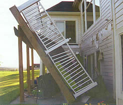
IMPROPERLY BUILT DECKS CAN BE VERY DANGEROUS. More than a million decks are built and replaced each year in the United States. While decks are a popular feature of many homes, the unsafe construction of decks has become a real concern within the building industry. Improper deck building has resulted in a growing number of deck failures and related injuries and deaths.
According to Don Bender the Director of the Wood Materials and Engineering Laboratory at Washington State University, “Decks cause more injuries and loss of life than any other part of the home structure.” Washington State Magazine’s article Making Decks Safer reports “Except for hurricanes and tornadoes, more injuries may be connected to deck failures than all other wood building components and loading cases combined.”
DO DECKS REALLY NEED TO MEET CODE REQUIREMENTS?
Because they look relatively simple to build, many people do not realize that decks are structures that need to be designed to adequately resist certain stresses. Like a house or any other building, a deck must be designed to support the weight of people and objects placed on them as well as lateral and uplift loads that can act on the deck as a result of wind or seismic activity. The 2006 versions of both the IBC and IRC contain language outlining the general design requirements of structures. This excerpt from the IRC represents a summary of the intent of both codes:
“The construction of buildings and structures in accordance with the provisions of this code shall result in a system that provides a complete load path that meets all requirements for the transfer of all loads from their point of origin through the load-resisting elements to the foundation.”
This concept of a complete or continuous load path refers to a series of solid connections within the structure of a deck that transfer load through its frame to the ground or adjacent, supporting structure (commonly a building). The same principle is applied to the design of all types of wood frame buildings. This continuous load path is created by using a system of structural connectors and fasteners to connect the wood members together.
5 THINGS TO LOOK FOR ON AN EXISTING DECK
- Missing Connectors: Any connections that do not meet the requirements can compromise the safety of the deck. In many cases toenailing does not constitute a proper connection.
- Loose Connections: Depending on how the deck was built, vital connections may have degraded over time due to various factors. Issues such as wobbly railings, loose stairs and ledgers that appear to be pulling away from the adjacent structure are all cause for concern.
- Corrosion of Connectors and Fasteners: Metal connectors and fasteners can corrode over time, especially if a product with insufficient corrosion resistance was installed.
- Rot: Wood can rot and degrade over time with exposure to the elements. Members within the deck frame that have rotted may no longer be able to perform the function for which they were installed.
- Cracks: As wood ages it is common for cracks to develop. Large cracks or excessive cracking overall can weaken deck framing members.
THE LIFE EXPECTANCY OF DECKS
Most experts agree that the average life expectancy of a deck is 10 to 15 years. Since deck building started about 30 years ago, there are many existing decks that are past their useful life. Deck maintenance is often overlooked as well. Decks are exposed to the elements, which can cause damage. It’s important that decks are properly inspected and maintained on a routine basis. If unsure, it’s best to consult with a professional, such as a structural engineer or contractor, to make sure the deck is safe.
LEDGER ATTACHMENT
Correct ledger attachment is crucial when building a deck that is attached to another structure. One of the most common causes for deck failure is ledgers that pull away from the primary structure, resulting in complete collapse.
The two most common ways to correctly attach a ledger to a structure are lag screws or through-bolts through the ledger and into the rim joist of the supporting structure. The installation of through-bolts requires access to the back side of the rim joist which, in some cases, is not possible without significant removal of drywall within the structure.
Code Requirements:
Where supported by attachment to an exterior wall, decks shall be positively anchored to the primary structure and designed for both vertical and lateral loads as applicable. Such attachments shall not be accomplished by the use of toenails or nails subject to withdrawal – IRC 2006 Section R502.2.2 / IBC 2006 Section 1604.8.3
DESIGN / INSTALLATION GUIDELINES
It is important that an engineer or other qualified professional evaluates the design of the deck to determine the specific number of fasteners and their spacing for any specific deck installation. The following installation requirements must be met:
- Screws must be installed into a stud or rim board with sufficient thickness.
- Screws can be installed over sheathing provided it is structural sheathing (OSB or plywood).
- Rim board must be at least 1½” thick or a reduction to the catalog loads is required.
- When installed into a stud, a minimum edge distance of 3/8” must be maintained.
- Minimum of 3” long screws must be used (plus the thickness of any structural sheathing that remains in place).
- Ledger must not be installed over siding or stucco, it must be fastened directly to the rim joist, stud, or sheathing.
FOOTINGS
In order for posts to properly resist various types of loads they must rest on, and be anchored to, concrete footings. Patios and pre-cast concrete piers do not qualify as proper footings for deck construction.
Code Requirements:
Footings:
The building codes include specific requirements regarding footing size that are dependent upon factors such as live and dead loads the deck is designed to resist as well as soil conditions. Footing should be designed per IRC 2006, Section R403 or IBC 2006, Section 1805
Minimum Footing Depths By Code
Footings shall be at least 12” below the undisturbed ground surface. IRC 2006, Section R403.1.4 / IBC 2006, Section 1805.2
Footings shall be designed so that the allowable bearing capacity of the soil is not exceeded. The minimum width of footings shall be 12 inches. IRC 2006, Section R403.1.1 / IBC 2006, Section 1805.4.1
Load Resistance
Columns shall be restrained to prevent lateral displacement at the bottom end. Wood columns shall not be less in nominal size than 4” X 4” – IRC 2006, Section R407.3
Column and Post-end Connections shall be fastened to resist lateral and net induced uplift forces – IBC 2006, Section 2304.9.7
Decay Resistance of Post
Wood Columns shall be of an approved wood with natural decay resistance or approved preservative-treated wood. Exception: Columns exposed to the weather that are supported by a metal pedestal projecting 1” above concrete and 6” above exposed earth – IRC 2006, Section R319.1 / IBC 2006, Section 2304.11
BEAM-TO-POST CONNECTIONS
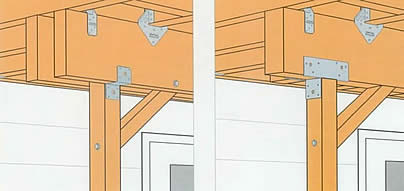
At the point where a beam meets a post, it must be properly connected to the post in order to resist gravity, lateral and uplift loads. This pertains to solid sawn beams or those comprised of multiple members, whether they rest on top or are fastened to the side of the post.
Code Requirements:
Where posts and beams or girder construction is used to support floor framing, positive connections shall be provided to ensure against uplift and lateral displacement – IRC 2006, Section R502.9 / IBC 2006, Section 2304.9.7
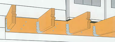
JOISTS TERMINATING INTO BEAM / LEDGER
When joists terminate into a beam or ledger, a connection is required to provide bearing. In cantilever applications the connection must also resist uplift.
Code Requirements:
Bearing
The ends of each joist, beam or girder shall have at least 1½” of bearing on wood or metal except where supported on a 1” X 4” ribbon strip nailed to adjacent studs. IRC 2006, Section R502.6 / IBC 2006, Section 2308.8.1
Joists framing into the side of a wood beam shall be supported by approved framing anchors or on ledger strips not smaller than 2” X 2” – IRC 2006, Section 502.6.2 / IBC 2006, Section 2308.8.2
Cantilevered Applications
Decks with cantilevered framing members, connections to exterior walls or other framing members shall be designed and constructed to resist uplift resulting from the full live load acting upon the cantilevered portion of the deck. IRC 2006, Section 502.2.2 / IBC 2006, Section 1604.8.3
JOISTS BEARING ON A BEAM
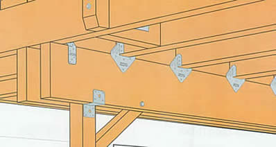
At the point where the joist bears on top of a beam, there must be a connection to resist lateral and uplift forces. Blocking or framing is also required thus preventing overturning of the joists.
Code Requirements:
Where posts and beam or girder construction is used to support floor framing, positive connections shall be provided to ensure against uplift and lateral displacement. IRC 2006, Section R502.9 / IBC 2006, Section 2304.9.7
Joists must be supported laterally at the ends by solid blocking or attachment to a full depth header, band or rim joist (IRC & IBC). Lateral restraint must be provided at each support (IRC only) IRC 2006, Section R502.7 / IBC 2006, Section 2308.8.2
RAILING POST-TO-DECK FRAMING
The railing connection is one of the more critical connections pertaining to safety, and it is often inadequately constructed. In order to provide the required load resistance at the hand rail, the post must not only be fastened to the rim joist, but also tied back into the joist framing. Machine bolts through the post and rim joist alone do not typically meet the performance requirements of the code.
Code Requirements:
When Required
Guards shall be located along open-sided walking surfaces, porches, balconied or raised floor surfaces more than 30’ above the floor or grade below. IRC 2006, Section R312.1 / IBC 2006, Section 1013.1
Height
Guards shall be a minimum of 36” (IRC) or 42” tall (IBC) IRC 2006, Section R312.1 / IBC 2006, Section 1013.2
Load Resistance
Handrail assemblies and guards shall be able to resist a single concentrated load of 200 pounds, applied in any direction at any point along the top (IRC & IBC), and have attachment devices and supporting structure to transfer this loading to appropriate structural elements of the building (IBC only) IRC 2006 Table R301.5 / IBC 2006, Section 1607.7.1
STAIR STRINGERS & TREADS
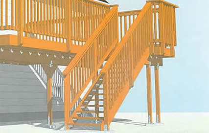
Stair stringers must be connected to the deck, and treads properly connected to the stringers, in order to resist loads. In addition, code requirements regarding openings between stairs treads and stair railings must also be met.
Code Requirements:
Stair Stringer to Rim Joist
Staircases must be able to resist 40 pounds per square foot of tread area. – IRC 2006, Table R301.5 / IBC 2006, Table 1607.1 (1 and 2 family dwellings.)
Stair Tread to Stringer
Individual stair treads shall be able to resist a 300 pound concentrated load over an area of 4 square inches. – IRC 2006, Table R301.5 / IBC 2006, Table 1607.1 (1 and 2 family dwellings.)
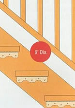 Railing to Stringer Opening Railing to Stringer Opening
The triangular openings formed by the riser, tread and bottom rail of the guard at the open side of the stairway shall be of a maxium size as not to allow a sphere 6” in diameter to pass through. – IRC 2006, Table R312.2 / IBC 2006, Table 1013.3
Source of information in this article: Simpson Strong-Tie Company, Inc.
<< Back to Technical Library |